Pneumatic valve System
The outlet of the pressure sequence valve remains closed until pressure upstream of it builds up to a predetermined value. The resistance can be reduced by expelling the exhausting air to the atmosphere quickly by using a Quick exhaust valve
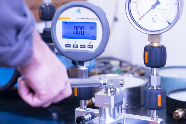
Pressure Control Valve
Compared with hydraulic systems, few pressure control valves are brought into use in pneumatics. Pistons, on the other hand, are generally more rugged and provide a larger effective sensing area in a given size regulator. The types of actuation vary;
Manually actuated
Mechanically actuated
Pneumatically/ air actuated
Electrically actuated
Combined actuation
The symbols of the methods of actuation are detailed in DIN ISO 1219. When applied to a directional control valve, consideration must be given to the method of initial actuation of the valve and also the method of return actuation. In many applications especially with single-acting cylinders, it is a common practice to increase the piston speed during retraction of the cylinder to save the cycle time. Output pressure accuracy is determined by the droop due to flow changes (regulator characteristics
. The higher speed of the piston is possible by reducing the resistance to the flow of the exhausting air during the motion of the cylinder.
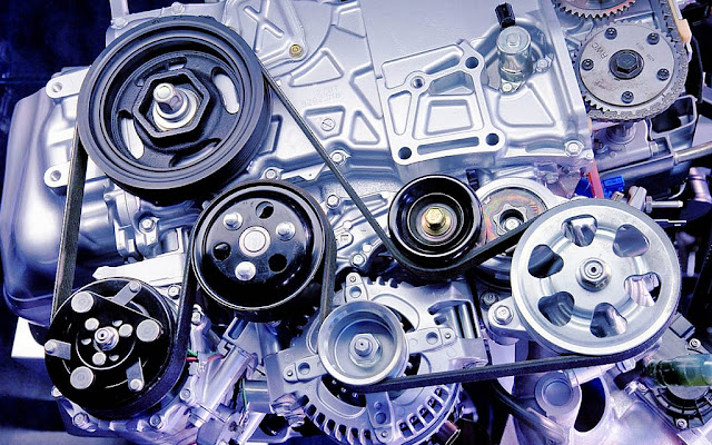
In order to control the movement of air actuators, compressed air has to be regulated, controlled, and reversed with a predetermined sequence.
Pressure and flow rates of the compressed air to be controlled to obtain the desired level of force and speed of air actuators.
The function of the directional control valve is to control the direction of flow in the pneumatic circuit. D C V are used to start, stop and regulate the direction of airflow and to help in the distribution of air in the required line.
As a signal element, the directional control valve is operated for example, by a roller lever to detect the piston rod position of the cylinder.
As a processing element, the directional control valve redirects or cancels signals depending on the signal input received.
As a control element, the directional control valve must deliver the required quantity of air to match the power component requirements.
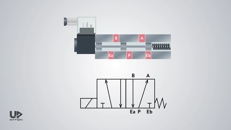
ISO Designation and Symbols of Direction Control Valves
The valve is described by the following methods:
The number of ports: 2-way, 3-way, 4-way, 5-way, etc.
The number of positions: 2 positions, 3 positions
Methods of actuation of the valve: Manually actuated, mechanically actuated, pneumatically actuated, or electrically actuated.
Methods of return action: Spring return, air return, etc.
Valves are represented by symbols because actual construction is quite complex. It is a standard feature of a compressed air production plant but is hardly ever used in pneumatic controls.
Pressure sequence valve
The function of the sequence valve is very similar to that of a pressure limiting valve. A symbol specifies the function of the valve, method of actuation, no of ports, and ways. The functional difference between precision and general-purpose regulators are the degree of control accuracy of the output pressure. Normally these are two separate methods. As soon as the inlet pressure in the direction of free flow develops a force greater than that of the internal spring, the check is lifted clear of the valve seat. They should be used where sensitive pressure settings are required (less than 0.0025 bar). For example Two-way, three-way, four-way valves.
Two-way Valve
Two-way valves are also simple two positions ON/OFF valves but actuated by actuators such as solenoid actuators, hydraulic actuators, etc.
Three-way valve
These valves have three nodes thats why named three-way valves and three-way valves allow two positions of actuation in ON condition
Five -way Valve
Four-way valve or two-position valves which got two-working positions for the actuators to control the flow direction.
Methods of actuation
The methods of actuation of pneumatic directional control valves depend upon the requirements of the task. A flow control valve regulates the rate of airflow. Types of Pneumatic Control Valves
Depending on the design, these can be divided into the following 4 categories:
Direction control valve
Non-return valves
Flow control valves
Pressure control valves
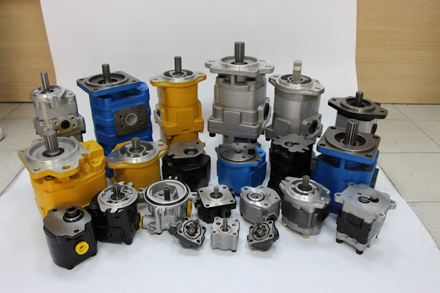
Direction Control Valve
Pneumatic systems like hydraulic systems also require control valves to direct and regulate the flow of fluid from the compressor to the various devices like air actuators and air motors. Pressure control valves control the pressure of the air flowing through the valve or confined in the system controlled
There may also be additional methods of actuation such as manual overrides, which are separately indicated
Non-return valves
Non-return valves permit the flow of air in one direction only, the other direction through the valve being at all times blocked to the airflow. Another standard ISO 1219-2:1995 establishes the rules for drawing diagrams of fluid power systems using symbols from ISO 1219-1. They are both shown on the symbol on either side of the position boxes. It is however used for a different purpose.
Flow Control Valves
The function of a flow control valve is self-evident from its name. Pneumatic symbols have been standardized in ISO 1219-1:2006. Mostly the valves are designed so that the check is additionally loaded by the downstream air pressure, thus supporting the non-return action.
Among the various types of non-return valves available, those preferentially employed in pneumatic controls are as follows:
Check valve
Shuttle valve
Quick exhaust valve
The simplest type of non-return valve is the check valve, which completely blocks airflow in one direction while permitting flow in the opposite direction with minimum pressure loss across the valve.
Port designations are described in ISO 5599.
Ports and position: D C V are described by the number of port connections or ways they control.
Diaphragms are generally more sensitive to pressure changes and react more quickly.
The control action is limited to the airflow passing through the valve when it is open, maintaining a set volume per unit of time.
There are three types of pressure control valves:
Pressure limiting valve
Pressure sequence valve
Pressure regulator or pressure reducing valve
Prevents the pressure in a system from rising above a permissible maximum. The check-in valve may be a plug, ball, plate, or diaphragm.
Quick Exhaust Valves
A quick exhaust valve is a typical shuttle valve.


Comments
Post a Comment