Mechanical Pressure Gauges
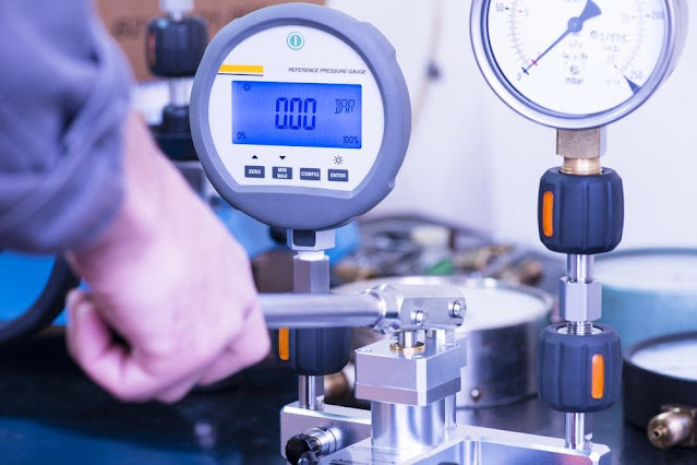
Types of Pressure Gauges Utility Pressure gauge Stainless steel pressure gauge Vibration-Proof ( Liquid filled ) Pressure gauge Low pressure capsule Pressure gauge More check

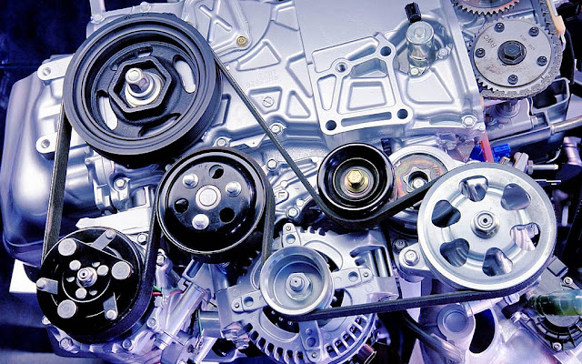
Hydraulic types of pumps
Types of hydraulic pumps
• Gear pump
• Piston pump
• Vane pump
• Clutch pump
• Screw pump
• Refuse pump
What is a gear pump?
A gear pump is a type of positive displacement (PD) pump. It moves a fluid by repeatedly enclosing a fixed volume using interlocking cogs or gears, transferring it mechanically using a cyclic pumping action.
It delivers a smooth pulse-free flow proportional to the rotational speed of its gears.
Generally, if the pump is expected to handle abrasive solids it is advisable to select a pump with a higher capacity so it can be operated at lower speeds to reduce wear.
The higher speeds and lower clearances of external gear designs make them unsuitable for these applications.
External gear pumps have four bearings in the pumped medium, and tight tolerances, so are less suited to handling abrasive fluids.
Since output is directly proportional to rotational speed, gear pumps are commonly used for metering and blending operations.
They work by building pressure then releasing it through an assembly that features a three-way directional control valve.
They are used for creating a smooth continuous flow, but the resistance encountered will inversely affect the performance
What are the limitations of a gear pump?
Gear pumps are self-priming and can dry-lift although their priming characteristics improve if the gears are wetted.
However, it should be borne in mind that the volumetric efficiency of a gear pump is reduced at lower speeds and flow rates.
A gear pump should not be operated too far from its recommended speed.
For high temperature applications, it is important to ensure that the operating temperature range is compatible with the pump specification.
it has the teeth projecting on the inside. Within this is a smaller external gear (the idler – only the rotor is driven) mounted off-centre.
This is designed to interlock with the rotor such that the gear teeth engage at one point.
A pinion and bushing attached to the pump casing holds the idler in position.
A fixed crescent-shaped partition or spacer fills the void created by the off-centre mounting position of the idler and acts as a seal between the inlet and outlet ports.
As the gears come out of mesh on the inlet side of the pump, they create an expanded volume.
Liquid flows into the cavities and is trapped by the gear teeth as the gears continue to rotate against the pump casing and partition.
The trapped fluid is moved from the inlet, to the discharge, around the casing.
As the teeth of the gears become interlocked on the discharge side of the pump, the volume is reduced and the fluid is forced out under pressure.
Gear pump


How does a gear pump work? Gear pumps use the actions of rotating cogs or gears to transfer fluids. The rotating element develops a liquid seal with the pump casing and creates suction at the pump inlet. Fluid, drawn into the pump, is enclosed within the cavities of its rotating gears and transferred to the discharge.
Piston pump


This pump type functions through a piston cup, oscillation mechanism where down-strokes cause pressure differentials, filling of pump chambers, where up-stroke forces the pump fluid out for use. Piston pumps are often used in scenarios requiring high, consistent pressure and in water irrigation or delivery systems.
Vane pump


HOW VANE PUMPS WORK. A vane pump uses a rotating cylinder with slots (or rotors) housing a series of vanes that rotate inside the cavity. The rotor is offset in a casing bore, so that when rotated, the vanes slide in and out. This creates expanding and contracting volumes that move liquid through the pump.
Clutch pump


The Hydraulic Clutch utilizes the fluid stored in the reservoir when the clutch pedal is pressed. The pushing force on the clutch pedal will force the piston inside the master cylinder and the fluid will be compressed to high pressure.
Screw pump


Screw pumps operate using two counter-rotating screw rotors which are engineered so that they rotate “towards each other”. This traps the gas in the space between the “screws” of their rotors. As the screws rotate, this trapped volume decreases which not only compresses the gas but moves it towards the exhaust
Refuse pump
What are the main features and benefits of a gear pump?
Gear pumps are compact and simple with a limited number of moving parts.
Gear pumps can be engineered to handle aggressive liquids. Gear pumps are particularly suited for pumping oils and other high viscosity fluids of the two designs,
external gear pumps are capable of sustaining higher pressures (up to 3000 psi) and flow rates because of the more rigid shaft support and closer tolerances.
The rotor is offset in a casing bore, so that when rotated, the vanes slide in and out. Generally, one gear is driven by a motor and this drives the other gear (the idler).
In some cases, both shafts may be driven by motors. The shafts are supported by bearings on each side of the casing.
As the gears come out of mesh on the inlet side of the pump, they create an expanded volume.
Liquid flows into the cavities and is trapped by the gear teeth as the gears continue to rotate against the pump casing.
fluid is transferred back through the centre, between the gears, because they are interlocked. Close tolerances between
the gears and the casing allow the pump to develop suction at the inlet and prevent fluid from leaking back from the discharge side (although leakage is more likely with low viscosity liquids
Internal gear pump

An internal gear pump operates on the same principle but the two interlocking gears are of different sizes with one rotating inside the other.
The larger gear (the rotor) is an internal gear i.e. The rotating element develops a liquid seal with the pump casing and creates suction at the pump inlet.
While they are commonly made from cast iron or stainless steel, new alloys and composites allow the pumps to handle corrosive liquids such as sulphuric acid, sodium hypochlorite, ferric chloride and sodium hydroxide
External gear pump

External gear pumps can also be used in hydraulic power applications, typically in vehicles, lifting machinery and mobile plant equipment.
The gears need to be lubricated by the pumped fluid and should not be run dry for prolonged periods.
Gear Pumps are the most common design, having fewer moving parts
Comments
Post a Comment