Mechanical Pressure Gauges
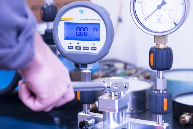
Types of Pressure Gauges Utility Pressure gauge Stainless steel pressure gauge Vibration-Proof ( Liquid filled ) Pressure gauge Low pressure capsule Pressure gauge More check

Hydraulic System basis Valve function
The valve is provided with an internal control passage to evaluate the outlet pressure (at port B).
When sufficient pilot pressure is applied, the spool moves against the spring force and opens the valve, thus allowing the flow through the valve.
They are designed to operate efficiently under extreme conditions and within wide-ranging temperatures.
Choosing the right hydraulic valve for your application is critical to securing the performance, reliability and lifespan of your system.
A pilot passage ‘x’ is provided in the valve to accept signals from the inlet to act on one side of the spool.
The flow path through the valve opens when the pressure at the pilot port increases beyond the pressure setting.
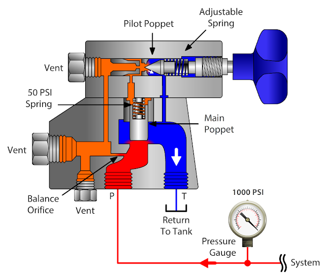
The main function of the counterbalance valve in a hydraulic circuit with a load-carrying actuator is to maintain the preset back pressure in the return line of the circuit, sufficient to balance the load held by the actuator.
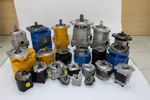
WE SUPPLY DIFFERENT TYPES OF HYDRAULIC VALVES
Directional Control Valves


Directional control valves can control the start, stop and change in direction of flow of a pressure medium (i.e. The unloading pressure can be varied by adjusting the spring tension.
When the outlet pressure remains below the valve setting,
the fluid flows freely from the inlet to the outlet (that is, from A to B). Pressure control valves can be Categories into:
(1) pressure reducing valves
(2) unloading valves
(3) sequence valves
(4) counterbalance valves
(5) brake valves.
Pressure Reducing Valve
The primary role of the pressure reducing valve in a hydraulic system is to limit the pressure in some part of the system to a value lower than that required for the rest of the system.
It also consists of a spring-loaded spool. When a sufficient signal is applied to the pilot spool, the spool shifts, and the pump delivery is diverted to the reservoir through the tank port (that is, from A to T) at a low-pressure. Valves should be sized correctly and selected based upon the purpose it is intended for – whether that’s for pressure relief or flow control.
Hydraulic valves are easily replaced within an existing circuit, but when designing a new hydraulic system this requires greater knowledge and understanding of the set expectations in order to select the correct product
The primary function of the unloading valve is to regulate the pressure by bypassing the fluid to the system reservoir at a low energy level in response to the external pressure signal received from the load section of the system
This helps to determine speed of movement for the hydraulic actuators.
Type of flow control valves
Flow controls, pressure compensated valves
Flow controls, throttle valve
About flow control valves
Sequence valves operate by directing the flow to another part of the hydraulic circuit when the set pressure is reached.
Unloading valves direct the flow back to the tank when the maximum pressure has been reached in a specific location of the circuit.
The most common types of flow control valves are gate valves, needle valves, diaphragm valves, pinch valves and globe valves.
In summary, hydraulic valves are a crucial component within any hydraulic system, no matter the scale or purpose of the application.
The counterbalance must be set at a little higher pressure than that required to retain the load. When the pressure at the outlet exceeds the valve setting, the spool shifts to block the outlet port, thus maintaining a reduced pressure in the regulated line.
Unloading Valve
An unloading valve consists of an inlet port ‘A’, a tank port ‘T’, a pilot port ‘X’, and a spring-biased spool. Hope you are able to recall the functions, circuits, and applications of pressure control valves.
Pressure control valves are used in hydraulic systems for obtaining pressure-related control functions. A pilot passage is provided to accept a signal from the load side of the valve and the signal acts on one side of the spool. The valve consists of an inlet port ‘A’, an outlet port ‘B’, a spring-loaded spool, and a pressure adjusting screw. The valve is kept open until the pilot sensing pressure goes below the spring bias. This occurs either gradually with variable throttle (control) or suddenly with a fixed throttle (switch).
Type of pressure control valves
Pressure relief valve

Symbol


Non return valve Or check valve


About pressure control valves
Proportional Control Valves
Proportional hydraulic valves are able to control the opening to flow proportionally instead of gradually, as is the case for most standard hydraulic valves.
Type of proportional control valves
Proportional directional control valves
Proportional pressure control valves
Proportional flow control valves
About proportional control valves
Flow Control Valves

Flow control valves manage the flow by decreasing or increasing the opening at the throttling point. The externally adjustable spring is provided to set the pressure. If you need help in choosing a hydraulic valve, we can help.
Primary Fluid Power are leading UK distributors of hydraulic components and fittings from best-in-class manufacturers, with a team of technical experts on hand ready to find the perfect solution for you. The valve remains closed by the spring force. When open, the valve discharges the fluid from the inlet port to the outlet port. In the normal position, the valve remains closed by the spring force. The externally adjustable spring is provided to set the pressure to the required value. They are available with built-in check valves each of that permits an unrestricted reverse flow. Unloading valves can be used in accumulator circuits, hydraulic motor circuits, and two-pump ‘hi-lo’ circuits.
Sequence Valve
A sequence valve consists of an inlet port ‘A’ an outlet port ‘B’, a spool and a spring. Hydraulic valves as poppet or spool valve.
Type of directional control valves
Directional poppet valves

Directional spool valves

Check and non-return valve
Pressure Control Valve types

Every pressure control valve switches at a predetermined pressure setting. hydraulic oil). The reduced pressure can be set by using a control spring. The spring chamber in the sequence valve is drained externally to the system reservoir to negate the effects of back pressure.
Counterbalance Valve


Symbol

The counterbalance valve is a normally-closed valve with an inlet port ‘A’ and an outlet port ‘B’. The pilot port is provided to accept the external pressure signal,
which acts on one end of the spring-biased valve spool. The valve closes when the pressure drops below the setting of the spring.
We have the in-house capabilities of building or modifying existing products to suit your exact specification.
The article looks at the basics of pressure control valves for educational use and is presented here to refresh your memory
Comments
Post a Comment